


Project KB: Mesh Waterfall Planning and Why Good 3D Design Saves You on Site
Project KB: Mesh Waterfall Planning and Why Good 3D Design Saves You on Site
When people ask me what matters most in a waterfall project, my answer is nearly always the same: planning.
Not pumps. Not stainless steel. Not filters. Not even the waterfall mesh itself.
Planning is the thing that saves you when the site changes, when access disappears, when you discover floor heating where you wanted to drill, or when a perfectly reasonable technical layout suddenly stops being possible because someone built a wall where there was no wall before.
That is exactly what happened on Project KB, a mesh waterfall installation where the whole technical setup had to be rethought quickly. The result is a good example of how modular waterfall systems, 3D planning, and flexible mounting details can turn a potential installation headache into something manageable.
💧 The basic mesh waterfall setup
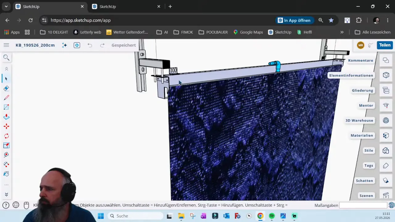
The starting point for this project is quite straightforward. At floor level, there is a mesh waterfall mounted into an overflow channel using mesh brackets. Water runs over the mesh surface and is collected at the bottom in a slim bottom tank, similar to the slim kit setup used in the shop system.
That gives us the core hydraulic arrangement:
- Waterfall mesh at normal ground level
- Overflow channel at the top
- Bottom collection tank below
- Technical tank handling pump, filtration, and water control
On top of that, multifunctional triangle brackets were added so decorative covers can later hide the bottom tank cleanly. That matters because a waterfall should not only work well, it should also look intentional and finished once the architect and customer add the visible design elements.
So far, so good. The concept was solid. Then reality entered the room.
🧱 The site changed, and the whole technical area had to change with it
But the bigger surprise was in the water treatment area. The original plan assumed access from the back side of the technical zone. That was important because the return line to the pump, the safety overflow, and other service points were arranged with that access in mind.
Then came the message: there is now a wall there.
No more rear access. Site visit in two weeks.
That is exactly the kind of moment where either your project falls apart or your planning system proves its value.
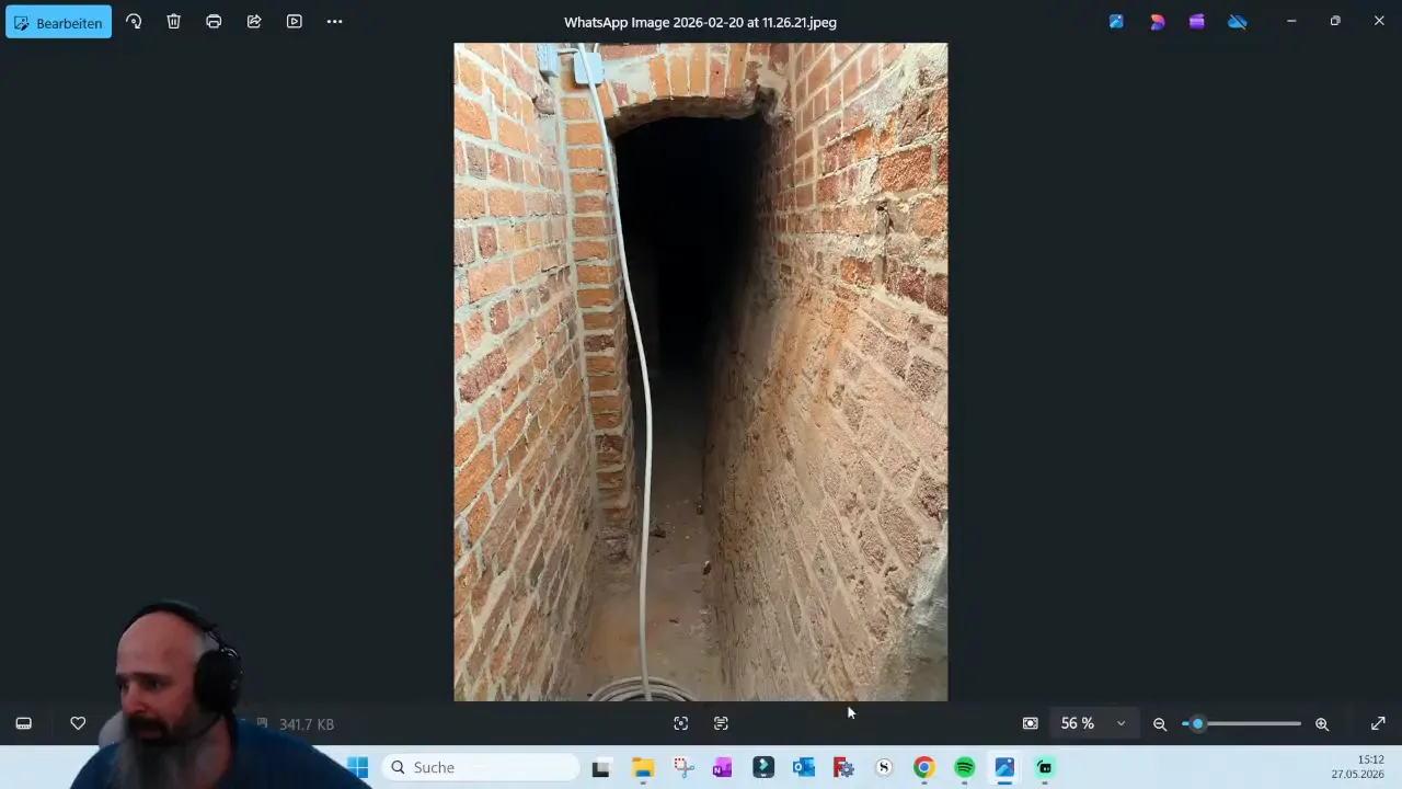
The technical area itself is unusual as well. It sits below ground level in an old basement-like space, so wastewater cannot simply run off by gravity. That means the system also needs a lifting pump for wastewater disposal, sending it up to the gravity drain line.
So this is not just a decorative waterfall. It is a compact technical system with real installation constraints:
- Limited space
- Changed access conditions
- No floor drilling
- Below-grade drainage challenges
- Need for future maintenance access
🔄 The solution: rotate the technical tank and redesign access
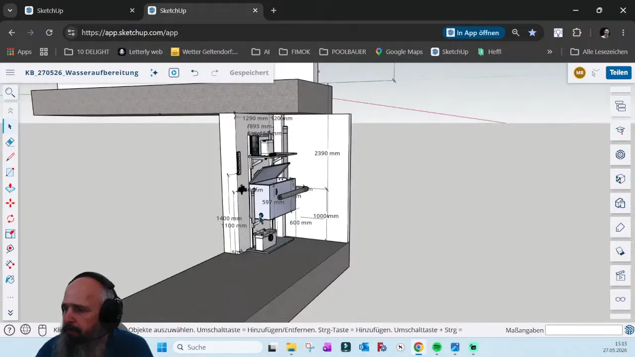
The redesign was simple in principle, but important in its consequences: the technical tank was turned 180 degrees.
That one decision changed everything. By rotating the tank, the connections for the backflow line and the safety overflow became accessible from the front side, which is the only side that will remain reachable later.
The reverse osmosis unit, water additive canister, and measuring unit were also moved upward. If these components had stayed lower down in the original position, they would have become nearly impossible to access with that new wall in place.
Good planning is not only about making something fit physically. It is about making sure someone can still reach the parts that need service months or years later.
That includes things like:
- Changing filters
- Replacing canisters
- Maintaining the backflow connection
- Checking the safety overflow
- Accessing the pump, dirt filter, and float valve
Electrical planning was also handled with the same practical mindset. The plugs were positioned high and away from likely splash zones. That sounds obvious, but on many sites people still place electrical connections right below valves or wet service points, which is asking for trouble.
Whenever water is involved, assume splashes will happen. Then place electrical points as far away as possible and ideally above the area where moisture could occur.
🛠️ Why flexible mounting systems matter so much
This project also shows why I like working with C profiles, consoles, and adjustable brackets.
On paper, drilling a hole into a concrete or masonry wall looks easy. On site, it often is not. You plan for one exact fixing point, start drilling, and then hit reinforcement, awkward brick joints, or some other surprise. Suddenly the perfect hole location is impossible.
That is how little construction dramas begin.
Using C profiles avoids a lot of that. Instead of relying on a single precise drilling point, the profile gives you many possible fixing holes while still keeping the system aligned with the plan. If one hole lands on steel reinforcement or a difficult spot in the wall, you simply use another.
The advantage is not only convenience. It is precision with flexibility.
In this project, that flexibility is used in several ways:
- The bottom tank is stabilized from the rear wall instead of the floor
- The mounting consoles can be adjusted up and down
- The tank position can move slightly forward or backward if required
- The technical tank can still be placed accurately even if wall drilling conditions are imperfect
This is especially useful when dealing with concrete walls, old brickwork, or any existing structure where the real site rarely behaves exactly like the drawing.
That is also why the larger C profiles in the technical area are so valuable. Even if drilling into the rear brickwork is awkward, the installer still has many hole positions available. That increases the chance that the profiles end up exactly where they should be before the final assembly team arrives.
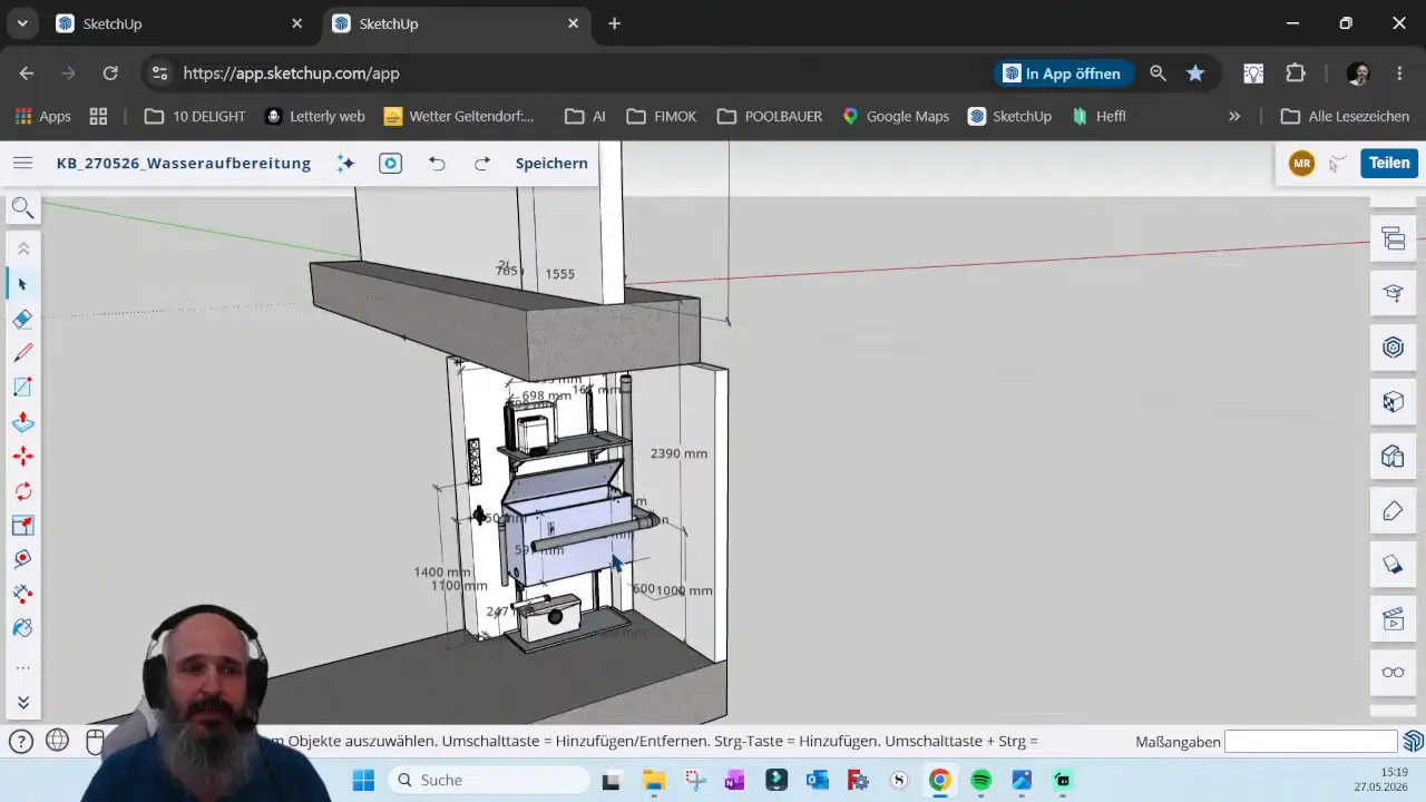
📐 Why SketchUp makes waterfall planning easier
Years ago, a lot of this kind of work was done in 2D, often by hand. It worked, but it also produced more mistakes. If a drawing is not fully to scale or if spatial relationships are not clear, it becomes much easier to misunderstand how parts will fit together.
With a 3D workflow in SketchUp, you can check the project in a much more realistic way. You can rotate the model, inspect clearances, test accessibility, and catch collisions before anyone shows up with tools and materials.
That is especially helpful for custom waterfall projects where almost every site has at least one surprise waiting.
Another big advantage is reuse. Once standard system components are modeled properly, they do not need to be drawn from scratch every time. Profiles, consoles, brackets, overflow channels, tanks, and support details can be copied into new projects and adjusted to suit the specific installation.
That means each new drawing becomes faster, more accurate, and more satisfying to build.
If you want to explore this specific planning model, you can open the 3D SketchUp file in the browser.
⚙️ Planning for installation is not enough, plan for maintenance too
One of the most common mistakes in water feature design is planning only until the day of installation.
But a waterfall is not finished when it is mounted. It has to be serviced, cleaned, adjusted, and maintained. Filters need replacement. Additives need refilling. Pumps may need inspection. Safety overflows and wastewater systems need to remain reachable.
So when I look at a technical layout, I ask a very practical question:
Can someone actually get their hands on all the important parts later?
If the answer is no, then the design is not finished yet.
That is why the final Project KB arrangement was organized so everything could be accessed from one side. The lifting device, reverse osmosis, additive system, technical tank, and pipe connections all had to remain serviceable from the front because the back would no longer be available.
🏗️ Modular systems are great, but custom thinking is still necessary
I believe in modular systems because they make projects faster, cleaner, and easier to scale. But modular does not mean one-size-fits-all.
Every real site brings custom conditions. In this case it was floor heating, an unexpected wall, difficult drainage, and restricted access. On another project it might be unusual dimensions, impossible drilling positions, or aesthetic requirements from an architect.
So even if you start with a kit, there is often still a need for custom planning and sometimes custom fabricated parts.
That can include:
- Adjusting support geometry
- Changing fixing strategies
- Relocating water treatment components
- Reworking pipe access routes
- Preparing weld-ready parts for local assembly
For some projects, it may even make sense to ship cut parts for local welding instead of sending a fully finished assembly. That can reduce cost and speed up delivery, especially when most of the material is already in stock and only needs to be cut to project size.
✅ The real lesson from Project KB
Project KB is a mesh waterfall planning example, but the lesson is bigger than waterfalls.
If you want a clean installation, fewer surprises on site, and a system that can still be maintained properly later, then design for change from the beginning.
That means:
- Use 3D planning so you can test fit, access, and collisions
- Expect site conditions to change even late in the project
- Build in flexibility with adjustable profiles and consoles
- Protect electrical connections from splash areas
- Plan for maintenance access, not just installation day
A well-designed waterfall system is not the one that only looks beautiful in the render. It is the one that still works when the site becomes awkward, the drilling is difficult, and the technical room is smaller than expected.
That is why planning comes first.
And when the planning is right, the installation becomes calmer, cleaner, and much more predictable.
Book a Consulting with Markus |
|
10min planning can save you 1 hour execution! |
| Shop Planning Packages Now! |


